more pictures
Attachments
-
 IMG_0380.JPG (1601.5 KB, 1 downloads) 15 years old
 - IMG_0360.JPG (1835.2 KB, 2 downloads) 15 years old
more pictures
:D
8O
vqjet - 7 seconds ago »
:lol:
:o
:D
:D
The brains
ACnMC - 1 week ago »
Thought i had copyright on the lunchbox idea .Good on yer :lol: :lol: ,they work well .boats looking good . might want to add a couple of drain holes if there aren`t any though .
Yeah its a great idea and works really well, had a few soakings and kept all the important bits dry!If I have breached your copy right maybe a ride in the boat would be fair retribution?
Well after pulling a few all nighters and working like mad I have finally got the boat to the stage where we can put the boat in the water. The team at Harris marine have done a fantastic job on all the parts they have supplied to me. I have taken the boat down to NZEFI a couple of times to get some base tuning done before we hit the river and tune it properly. There have been a few issues we have struck along the way, as was to be expected.
We were having major issues with the cooling system, the temp would climb and climb until the system would boil with no sign of the thermostat opening. I thought it was a stuck thermostat and being a very unique design had to get a genuine one down from Auckland, it was actually way cheaper than the Repco alternative 8O
Put the new thermostat in and same thing was happening, phoned Nissan and they have never had a dud factory thermostat that they knew of, but did tell me that this motor does run very hot, low to mid 90s when hoked up to the factory diagnostic computer and the thermostat doesn't open till approx 100 on the computer. Sounded very strange to me, that is awfully hot for a motor to be running!
To cut a long story short it turned out that I had the cooling system plumed incorrectly, the heater circuit needs to be included as this routs the only hot water around the thermostat until it opens. I had all this blocked off as thought it was not necessary. So without the heater circuit no hot water was getting to the thermostat. I found a copy of the genuine Nissan VQ35DE engine manual on the internet, this was very helpful.
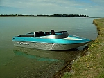
This is how the new cooling circuit looks. I have had the motor up to operating temp now, the gauge on the dash reads about 81 - 85 but when I hook the laptop up to the computer it tells me the engine is running at 91-95, the sensors are about 30mm apart. I am guessing the computer is reading on the high side which seems strange? Here are some pictures of the boat as of today.
:-) :-)
We took the boat down to the river to see how it was all working, went really well so decided to take it off the trailer for the first time. It sounds great, we didn't push it to hard and didn't go past 2500 Rpm as the motor is still way out of tune. Goes great! At 2500 rpm its up on plane and going well!! I think we have finally sorted out all the little bugs! Yippee!! :-) The 12 degree hull handles beautifully, think it was a good choice. We are heading back down to the river on Tuesday to give it the big tune with all the sensors hooked up (O2, knock ect) and after that hopefully going on some big trips. Will let you know how it goes after Tuesday (will be taking the GPS down as well).
We took the boat down to the ramp this morning for tuning. Went well and had some runs up the river. The hull handles very nicely, and gets out of the hole and onto plane very fast. Then this afternoon we took the boat up to Woodstock to take some passengers for a much anticipated ride. Lots of fun and got the GPS out to see what the top speed is.
:-) :D
:lol:
8O
And the top speed on the GPS down stream (WOT = 5800 RPM);
60 L of fuel and two on board
- 95kph
60L of fuel and one on board
- 98.3kph
This boat goes fantastic, has heaps of punch and goes very shallow, love it!
<object width="425" height="344"><param name="movie" value="http://www.youtube.com/v/3icfwDlK8R8&hl=en&fs=1"></param><param name="allowFullScreen" value="true"></param><param name="allowscriptaccess" value="always"></param><embed src="http://www.youtube.com/v/3icfwDlK8R8&hl=en&fs=1" type="application/x-shockwave-flash" allowscriptaccess="always" allowfullscreen="true" width="425" height="344"></embed></object>
[code]<object width="425" height="344"><param name="movie" value="http://www.youtube.com/v/3icfwDlK8R8&hl=en&fs=1"></param><param name="allowFullScreen" value="true"></param><param name="allowscriptaccess" value="always"></param><embed src="http://www.youtube.com/v/3icfwDlK8R8&hl=en&fs=1" type="application/x-shockwave-flash" allowscriptaccess="always" allowfullscreen="true" width="425" height="344"></embed></object>
Yeah I'm very happy! Has totally exceeded my expectations, Scott have produced a brilliantly handling hull and the guys at Harris marine have done a fantastic job on all the parts.
Hi, I haven't put put any comments on here for quiet a while but have been watching with great interest.
Me and Dad haven't got a boat sorted yet but are about to start the hunt again for a winter project What has sparked my interest is me and Dad put a VQ35 into our beach buggy/off roader. we have got a link Storm for the spark and fuel.
We are having some problems with the crank and 2 cam sensor wiring, Dad spoke to Link and they said that they are Hall/optical sensors and have a 12v supply . Dad thinks they are reluctor sensors. Can you help me and tell me the wiring for these sensors?
I will try to get some photos up of our buggy, should be a rocket if we get it going
Hay, sounds like a cool project, NZEFI did most of the wiring for us, they were great to deal with and will definitely be able to help you out. I also have the 2005 Nissan VQ35 factory workshop manual which is loaded with all sorts of great info, will have a look and see what I can find.
I found this info in the factory manual, will see if I can find some wiring pictures.
"DTC P0335 CKP SENSOR (POS) PFP:23731
Component Description UBS0095M
The crankshaft position sensor (POS) is located on the oil pan facing
the gear teeth (cogs) of the signal plate. It detects the fluctuation of
the engine revolution.
The sensor consists of a permanent magnet and Hall IC.
When the engine is running, the high and low parts of the teeth
cause the gap with the sensor to change.
The changing gap causes the magnetic field near the sensor to
change."
Due to the changing magnetic field, the voltage from the sensor
changes.
The ECM receives the voltage signal and detects the fluctuation of
the engine revolution.
You must log in to post.